Procedural Investigations in webGL – Section IV

Section IV
Getting Noisy in Here

Finally the part I have been wanting to get to! One of the power players in the procedural world are methods called noise. Noise is a random (in our case pseudorandom) distribution of values over a range. Normally these values range from -1 to 1, but can have other values. We use these predictably random functions to control our methods. The simplest, yet least useful to use will be a white noise function, which some of you should be familiar with. Picture your old analog TV set to a blank channel or the scene from the movie Poltergeist.

Example

There has been quite a bit of advancement in the generation of random values, with the works of Steven Worley and Ken Perlin. We can use a combination of their methods, to achieve some really interesting results. The are two main types of noise that we will be covering are lattice and gradient based noise methods.

Lattice Noise/Value Noise

There is a little bit of confusion in the procedural world with what is a value based noise and what is gradient. This is demonstrated by the article we will be referencing calls the process we will be reviewing [1] Perlin when it is actually Value Noise.

Value Noise is a series of nDimensional points at a set frequency that have a value, we then interpolate between the points which then gives us our values. There are multiple ways to interpolate the values and most do it smoothly but to help you understand the concept lets temporarily do a linear interpolation.

Take for example if we had a 1D noise with our lattice set at every integer value and a linear interpolation we get a graph similar to this:

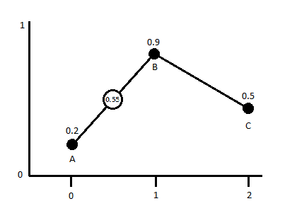
If we were to sample any point now between any of the lattice points we would get a value between the values of the closets points. In this 1d grid it would be the two closest points, in a 2d grid it would be 4 and in a 3d grid it would be 6 (for 2d/3d you can sample more but these are the minimum neighborhoods). So if we were to sample from this 1d Noise at the coordinate x=1.5 we would end up with a value of 0.55 (unless my math sucks).

If we use this process and mix together value noises of increasing frequency and decreasing amplitude we can make some interesting results. Another parameter we can introduce for control is persistence, which has some confusion as well as to its “official” definition. The term was first used by Mandelbrot while developing fractal systems. The simplest way to describe it would be the weighted effect of the values on the sum of the noise functions.

Random Function

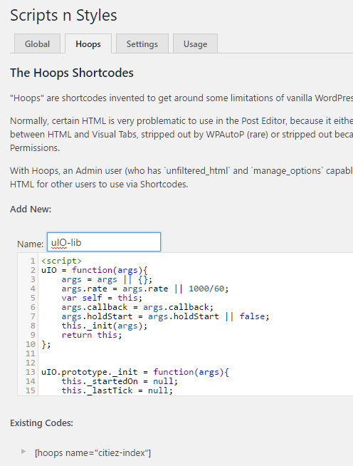
In order to get our noise functions rolling we first need to create a random number generation method. Here is a section of pseudo-code presented in [1]:

function IntNoise(32-bit integer: x)
    x = (x<<13) ^ x;
    return ( 1.0 - ( (x * (x * x * 15731 + 789221) + 1376312589) &#038; 7fffffff) / 1073741824.0);
end IntNoise function

Right away one should notice that this is very close to the code that we used for the white noise generator above. There are many ways to generate a random number but we will convert this one initially and then test other methods to see which are more effective.
The GLSL version of this code would be:

float rValueInt(int x){
    x = (x >> 13) ^ x;
    int xx = (x * (x * x * 60493 + 19990303) + 1376312589) & 0x7fffffff;
    return 1.0 - (float(xx) / 1073741824.0);
}

This function requires our input value to be an integer (hence making it a lattice), we then use bit-wise operators as explained in GLSL specs[2]. I have no clue what is really happening with the bit-wise stuff other then we are shifting the number around… sorry I dont know more. The numbers that we used are right from Hugos example [1] and are prime numbers. You can change these numbers all you want, just make sure you keep them as prime in order to prevent as noticeable of graphic artifacts. From here we just need to decide how we want to interpolate the values between points.

Its all up to Interpolation…

The simplest way to interpolate is linearly like what we used above is represented by this equation:

Mock CodeGLSL Code


function Linear_Interpolate(a, b, x)
	return  a*(1-x) + b*x
  end of function

float linearInterp(float a, float b, float x){
	return a*(1.-x) + b*x;
}

This is ok if we want sharp elements, but if we want smoother transitions we can use a cosine interpolation.

function Cosine_Interpolate(a, b, x)
    ft = x * 3.1415927
    f = (1 - cos(ft)) * .5
    return  a*(1-f) + b*f
end of function
float cosInterp(float a, float b, float x){
	float ft = x*3.12159276;
	float f = (1.0 - cos(ft)) * .5;
	return a*(1.-f) + b*f;
}

There is also cubic iterp, but we will skip that for now and focus on linear and cosine. The last thing we will want to do, in order to make our noises smoother on their transitions is introduce a you guessed it smoothing function. This function can optionally be used and can be expanded to how ever many dimensions you would need. The smoothing helps reduce the appearance of block artifacts when rendering out to 2+ dimensions. Here is a snip-it of pseudo-code from [1].


//1-dimensional Smooth Noise
  function Noise(x)
    ...    .
  end function

  function SmoothNoise_1D(x)
    return Noise(x)/2  +  Noise(x-1)/4  +  Noise(x+1)/4
  end function

//2-dimensional Smooth Noise
function Noise(x, y)
...
end function

function SmoothNoise_2D(x>, y)

    corners = ( Noise(x-1, y-1)+Noise(x+1, y-1)+Noise(x-1, y+1)+Noise(x+1, y+1) ) / 16
    sides   = ( Noise(x-1, y)  +Noise(x+1, y)  +Noise(x, y-1)  +Noise(x, y+1) ) /  8
    center  =  Noise(x, y) / 4

    return corners + sides + center

end function

Later in this section we will look at the differences between smoothed and non-smoothed noise. Now we need to start taking all these elements and put them together. Here is the pseudo code as exampled by [1]


function Noise1(integer x)
    x = (x<<13) ^ x;
    return ( 1.0 - ( (x * (x * x * 15731 + 789221) + 1376312589) &#038; 7fffffff) / 1073741824.0);    
  end function


  function SmoothedNoise_1(float x)
    return Noise(x)/2  +  Noise(x-1)/4  +  Noise(x+1)/4
  end function


  function InterpolatedNoise_1(float x)

      integer_X    = int(x)
      fractional_X = x - integer_X

      v1 = SmoothedNoise1(integer_X)
      v2 = SmoothedNoise1(integer_X + 1)

      return Interpolate(v1 , v2 , fractional_X)

  end function


  function PerlinNoise_1D(float x)

      total = 0
      p = persistence
      n = Number_Of_Octaves - 1

      loop i from 0 to n

          frequency = 2i
          amplitude = pi

          total = total + InterpolatedNoisei(x * frequency) * amplitude

      end of i loop

      return total

  end function

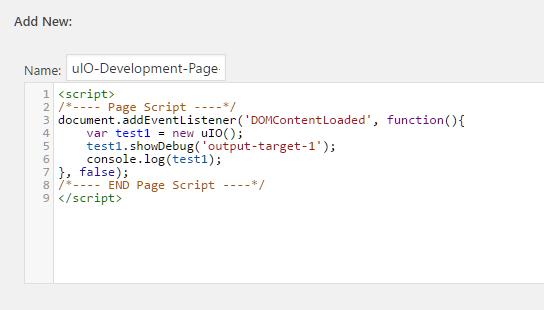
I decided to make a few structural changes to this for the GLSL conversion. In the above example they use four functions to make it happen, we are going to do it with three. I think it will also be relevant to add uniforms (or defines depends on your preference) to control things like octaves, persistence and a smoothness toggle. I will also be using strictly the cos interpolation, this is by personal choice any method can be used though. So following the structure of our SM object, we set up the shader argument as follows:


sm = new SM(
{
size : new BABYLON.Vector2(512, 512),
hasTime : false,
//timeFactor : 0.1,
uniforms:{
	octaves:{
		type : 'float',
		value : 4,
		min : 0,
		max : 124,
		step: 1,
		hasControl : true
	},
	persistence:{
		type : 'float',
		value : 0.5,
		min : 0.001,
		max : 1.0,
		step: 0.001,
		hasControl : true
	},
	smoothed:{
		type : 'float',
		value : 1.0,
		min : 0,
		max : 1.0,
		step: 1,
		hasControl : true
	},
	zoom:{
		type : 'float',
		value : 1,
		min : 0.001,
		step: 0.1,
		hasControl : true
	},
	offset:{
		type : 'vec2',
		value : new BABYLON.Vector2(0, 0),
		step: new BABYLON.Vector2(1, 1),
		hasControl : true
	},
},
fx :
`precision highp float;
//Varyings
varying vec2 vUV;
varying vec2 tUV;
/*----- UNIFORMS ------*/
uniform float time;
uniform vec2 tSize;
uniform float octaves;
uniform float persistence;
uniform float smoothed;
uniform float zoom;
uniform vec2 offset;

This will set up all of our uniforms and the defaults for them. You can do these as defines, but if having the ability to manipulate it on the fly they should be uniforms. I also added a uniform that we will not be manipulating directly ever but letting the size of the canvas/texture set this value when the shader is compiled. With this we need to make some changes to our SM object to accommodate this new uniform.

SM = function(args, scene){	
	...
	this.buildGUI();
	
	this.setSize(args.size);
	
	return this;
}

SM.prototype = {
...
setSize : function(size){
	var canvas = this.scene._engine._gl.canvas;
	size = size || new BABYLON.Vector2(canvas.width, canvas.height);
	this._size = size;	
	var pNode = canvas.parentNode;
	pNode.style.width = size.x+'px';
	pNode.style.height = size.y+'px';
	this.scene._engine.resize();
	this.buildOutput();
	this.buildShader();
}
...

Now the shader will always know what the size of the texture is, because we have made this a inherent feature of the SM object we need to add the uniform for tSize to the default fragment that the shader has built in. This is in the situation that the default shader get bound that it will validate and compile. From here we need to include our random number function, our interpolation function and the noise function itself. I am going to include a lerp function as well in case you want to use this and the interpolation vs cos.

//Methods
//1D Random Value from INT;
float rValueInt(int x){
	x = (x >> 13) ^ x;
	int xx = (x * (x * x * 60493 + 19990303) + 1376312589) & 0x7fffffff;
	return 1. - (float(xx) / 1073741824.0);
}
//float Lerp
float linearInterp(float a, float b, float x){
	return a*(1.-x) + b*x;
}
//float Cosine_Interp
float cosInterp(float a, float b, float x){
	float ft = x*3.12159276;
	float f = (1.0 - cos(ft)) * .5;
	return a*(1.-f) + b*f;
}
//1d Lattice Noise
float valueNoise1D(float x, float persistence, float octaves, float smoothed){
float t = 0.0;
float p = persistence; 
float frequency, amplitude, tt, v1, v2, fx;
int ix;
for(float i=1.0; i<=octaves; i++){
	frequency = i*2.0;
	amplitude = p*i;
	
	ix = int(x*frequency);	
	fx = fract(x*frequency);
	
	if(smoothed > 0.0){
		v1 = rValueInt(ix)/2.0 + rValueInt(ix-1)/4.0 + rValueInt(ix+1)/4.0;
		v2 = rValueInt(ix+1)/2.0 + rValueInt(ix)/4.0 + rValueInt(ix+2)/4.0;		
		tt = cosInterp(v1, v2, fx);
	}else{
		tt = cosInterp(rValueInt(ix), rValueInt(ix+1), fx);
	}
	
	t+= tt*amplitude;	
}
t/=octaves;
return t;
}

So now we have a GLSL function to generate some 1D noise! It has four arguments, the last one of smoothed can be omitted if you please but I like having it so…. It a fairly simple function and most of our noise functions will have a similar structure. We could also put a #define in that would control the interpolation, but for simplicity I am just using the cosine method. From here it is as simple as setting up the main function of our shader program to use this noise. To do this we decide our sampling space and pass that to the x value of the noise function along with our other uniforms that we have already set up.

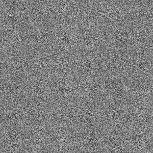
void main(void) {
	vec2 tPos = ((vUV*tSize)+offset)/zoom;
	float v = valueNoise1D(tPos.x, persistence, octaves, smoothed)+1.0/2.0;
	vec3 color = vec3(mix(vec3(0.0), vec3(1.0), v)); 	
    gl_FragColor = vec4(color, 1.0);	
}

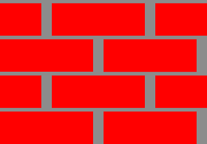
Super easy right!? Our sampling space that we use is the 0-1 uv multiplied by the size of the texture, which effectively shifts us to texel space. The choice to use to vUV instead of the tUV was because for some reason the negative value was creating an artifact as seen here:

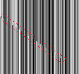
I could try to trouble shoot that, but instead its just easier to use the 0-1 uv range and move on.

Next add an offset which is also in texel space, you could do it as a percentage of the texture’s size but that is user preference. We then divide the whole thing by a zoom value. That gives us a nice sampling space, which we then pass to our noise function with our other arguments. Because the noise function returns a number between negative 1 and positive 1, we shift it to a 0-1 range by simply adding one then dividing the sum by two.

A New Dimension

One dimensional noise is cool and has its uses, but we need more room for activities. Before we develop more noises and look at different methods for generation having an understanding of how to extend the noise to n-dimensions is pretty important. For all general purposes all calculations stay the same, you just have to make a couple more of them. It would probably be smart to add a support function for smoothing the values of the interpolation now that we are working with larger dimensions. The main modifications to the function will be changing some of the variables from floats and integers to vectors of the same type. The last function to add is a random number generator that takes into consideration the 2 dimensions.

//2D Random Value from INT vec2;
float rValueInt(ivec2 p){
	int x = p.x, y=p.y;
	int n = x+y*57;
	n = (n >> 13) ^ n;
	int nn = (n * (n * n * 60493 + 19990303) + 1376312589) & 0x7fffffff;
	return 1. - (float(nn) / 1073741824.0);
}

float smoothed2dVN(ivec2 pos){
return (( rValueInt(pos+ivec2(-1))+ rValueInt(pos+ivec2(1, -1))+rValueInt(pos+ivec2(-1, 1))+rValueInt(pos+ivec2(1, 1)) ) / 16.) + //corners
	   (( rValueInt(pos+ivec2(-1, 0)) + rValueInt(pos+ivec2(1, 0)) + rValueInt(pos+ivec2(0, -1)) + rValueInt(pos+ivec2(0,1)) ) / 8.) + //sides
	   (rValueInt(pos) / 4.);
}

//2d Lattice Noise
float valueNoise(vec2 pos, float persistence, float octaves, float smoothed){
float t = 0.0;
float p = persistence; 
float frequency, amplitude, tt, v1, v2, v3, v4;
vec2 fpos;
ivec2 ipos;
for(float i=1.0; i<=octaves; i++){
	frequency = i*2.0;
	amplitude = p*i;
	
	ipos = ivec2(int(pos.x*frequency), int(pos.y*frequency));	
	fpos =  vec2(fract(pos.x*frequency), fract(pos.y*frequency));
	
	if(smoothed > 0.0){
		ivec2 oPos = ipos;
		v1 = smoothed2dVN(oPos);	
		oPos = ipos+ivec2(1, 0);
		v2 = smoothed2dVN(oPos);
		oPos = ipos+ivec2(0, 1);
		v3 = smoothed2dVN(oPos);	
		oPos = ipos+ivec2(1, 1);
		v4 = smoothed2dVN(oPos);
		
		float i1 = cosInterp(v1, v2, fpos.x);
		float i2 = cosInterp(v3, v4, fpos.x);
		tt = cosInterp(i1, i2, fpos.y);

	}else{
		float i1 = cosInterp(rValueInt(ipos), rValueInt(ipos+ivec2(1,0)), fpos.x);
		float i2 = cosInterp(rValueInt(ipos+ivec2(0,1)), rValueInt(ipos+ivec2(1,1)), fpos.x);
	
		tt = cosInterp(i1, i2, fpos.y);
	}
	
	t+= tt*amplitude;	
}
t/=octaves;
return t;
}

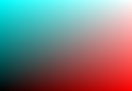
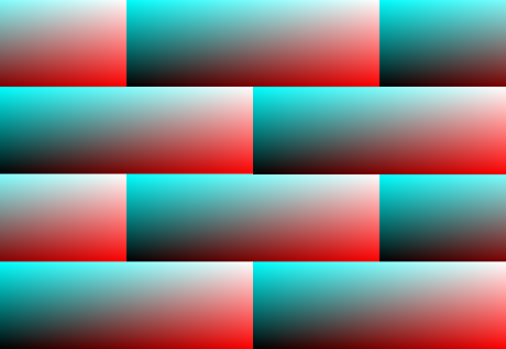
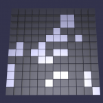
There we have it, there are definitely some problems with this method that if we took some time and refined this could be fixed. These problems are things like artifacts as the noise transfers from a positive to a negative coordinate range which is apparent the more you zoom in and noticeable circular patterns the closer to 0,0 we get. In order to fix this quickly and essentially ‘ignore’ that problem we just add a large offset to the noise initially and screw our coordinates to be far away from the artifacts.

As a challenge see if you can change the interpolation function to be cubic. Read the section on it here [3].

You can also see a live example of the 2d Lattice Noise here.

Better Noise from Gradients

References

1. Hugo Elia’s “Perlin noise” implementation. Value Noise, mislabeled as Perlin noise.
2. https://www.khronos.org/registry/OpenGL/specs/gl/GLSLangSpec.1.20.pdf
3. C# Noise

Procedural Investigations in webGL – Section III

Section III
Advance Spaces, Time and Polar


With our new SM object put together we now have the ability to start putting together a collection of generators and other GLSL functions to create more dynamic content. If we go back to our reference book [1] starting on page 46 it starts reviewing some interesting methods we will recreate now.

Star of My Eye


For practice a great project is to create a star shape. At first glance one might think that it would be tough to generate something like this, but once we shift our sampling space to be in polar coordinates through cos/sin (sinusoidal) calculations. Again my version will be a variation of a segment of script meant for Renderman. I will show the RSL (Renderman Shader Language) version from [1] next to my GLSL version then review the differences. I would recommend going through line by line and try to recreate this on your own.


surface star(
    uniform float Ka = 1;
    uniform float Kd = 1;
    uniform color starcolor = color (1.0000,0.5161,0.0000);
    uniform float npoints = 5;
    uniform float sctr = 0.5;
    uniform float tctr = 0.5;
){
    point Nf = normalize(faceforward(N, I));
    color Ct;
    float ss, tt, angle, r, a, in_out;
    uniform float rmin = 0.07, rmax = 0.2;
    uniform float starangle = 2*PI/npoints;
    uniform point pO = rmax*(cos(0),sin(0), 0);
    uniform point pi = rmin*(cos(starangle/2),sin(starangle/2),0);
    uniform point d0 = pi - p0; point d1;
    ss = s - sctr; tt=t- tctr;
    angle = atan(ss, tt) + PI;
    r = sqrt(ss*ss + tt*tt);
    a = mod(angle, starangle)/starangle;
    if (a >= 0.5) a = 1 - a;
    dl = r*(cos(a), sin(a),0) - p0;
    in_out = step(0, zcomp(d0^d1) );
    Ct = mix(Cs, starcolor, in_out);
    /* diffuse (“matte”) shading model */
    Oi = Os;
    Ci = Os * Ct * (Ka * ambient() + Kd * diffuse(Nf));
}

precision highp float;
//Varyings
varying vec2 vUV;
varying vec2 tUV;
//Methods
/*----- UNIFORMS ------*/
#define PI 3.14159265359
uniform vec3 starColor;
uniform float nPoints;
uniform float rmin;
uniform float rmax;
uniform float aaValue;
uniform vec3 bgColor;

void main(void) {
	vec2 offsetFix = vec2(0.5);	
	float ss, tt, angle, r, a;
	vec3 color = bgColor;		
	float starAngle = 2.*PI/nPoints;	
	vec3 p0 = rmax*vec3(cos(0.),sin(0.), 0.);
	vec3 p1 = rmin*vec3(cos(starAngle/2.),sin(starAngle/2.), 0.);	
	vec3 d0 = p1 - p0;
	vec3 d1;	
	
	ss = vUV.x - offsetFix.x; tt = (1.0 - vUV.y) - offsetFix.y;
	angle = atan(ss, tt) + PI;	
	r = sqrt(ss*ss + tt*tt);		
	a = mod(angle, starAngle)/starAngle;
	
	if (a >= 0.5){a = 1.0 - a;}
	
	d1 = r*vec3(cos(a), sin(a), 0.) - p0;
	
	float in_out = smoothstep(0., aaValue, cross(d0 , d1).z);	

	color = mix(color, starColor, in_out);	

    gl_FragColor = vec4(color, 1.0);	
}

Some of the values in the RSL version are irrelevant to us, like Ka, Kd, Nf, Oi, Ci and any other variables accosted with a light model. Things that are important to us are the number of points the star will have, its size limits, and our colors. Lets go through the GLSL version line by line and understand what is going on.

First we have our precision mode, which we want as accurate as floats as possible so we keep it as highp. The varying section is pretty standard, we could remove the tUV as its not used but we will keep it as you may want to sample in the -1 to 1 range instead of 0 to 1 in some instances. No additional methods need to be defined. The uniforms section includes a definition for PI, because we are going to be working in polar space and be using calculations dependent on circular/spherical values. GLSL does not define this value inherently and so it is up to us to make sure we have a value we can reference; the cool part about this is we can experiment with funky values and see how that effects our calculations (PI = 4, for example).

The main function of the program starts with up setting a value for the offset fix of the star, which we will use later to move the sample into a scope that will ‘center’ the star. Then we define a few floats that will be used later, they could be defined at time of execution of the line this just makes things more readable. I cant even lie, I do not understand this math in the slightest… I understand some of it, but for the most part I just translated it from RSL to GLSL. Even the explanation in [1] is kinda crap as well. If any math buffs are reading this and want to do a break down of wtf is going on with these numbers and can send me an email, I will love you long time.

At the very least here is a snippet of the summary from [1]:

To test whether (r,a) is inside the star, the shader finds the vectors d0 from the
tip of the star point to the rmin vertex and d1 from the tip of the star point to the
sample point. Now we use a handy trick from vector algebra. The cross product of
two vectors is perpendicular to the plane containing the vectors, but there are two
directions in which it could point. If the plane of the two vectors is the (x, y) plane,
the cross product will point along the positive z-axis or along the negative z-axis.
The direction in which it points is determined by whether the first vector is to the left
or to the right of the second vector. So we can use the direction of the cross product
to decide which side of the star edge d0 the sample point is on.

Yeah… what that says… Its pretty much a distance function, anyways one improvement I included was the ability to anti-alias the edges. This is very simple, we just change out the step calculation for a smoothstep one with a decently low value to represent the tolerance.

There are other ways to go about this but for now this will do. Mess around with this a little bit see what you can figure out. For a live example you can go here.

Head in the Clouds & Introducing Time


Another common procedural processes would be the creation 2d/3d clouds. There are way to many solutions for this then I could count, but a very simple implementation would be to layer multiple sinusoidal functions at different frequencies. I think now would be a good time to implement some time shifting to our shader as well. We will use this time shift to animate the clouds. Once again lets take a look at the RSL version provided in [1] and compare it to my GLSL solution.


#define NTERMS 5
surface cloudplane(
    color cloudcolor = color (1,1,1);
)
{
    color Ct;
    point Psh;
    float i, amplitude, f;
    float x, fx, xfreq, xphase;
    float y, fy, yfreq, yphase;
    uniform float offset = 0.5;
    uniform float xoffset = 13;
    uniform float yoffset = 96;
    Psh = transform(“shader”, P);
    x = xcomp(Psh) + xoffset;
    y = ycomp(Psh) + yoffset;
    xphase = 0.9; /* arbitrary */
    yphase = 0.7; /* arbitrary */
    xfreq = 2 * PI * 0.023;
    yfreq = 2 * PI * 0.021;
    amplitude = 0.3;
    f = 0;
    for (i = 0; i < NTERMS; i += 1) {
        fx = amplitude * (offset + cos(xfreq * (x + xphase)));
        fy = amplitude * (offset + cos(yfreq * (y + yphase)));
        f += fx * fy;
        xphase = PI/2 * 0.9 * cos (yfreq * y);
        yphase = PI/2 * 1.1 * cos (xfreq * x);
        xfreq *= 1.9+i* 0.1; /* approximately 2 */
        yfreq *= 2.2-i* 0.08; /* approximately 2 */
        amplitude *= 0.707;
    }
    f = clamp(f, 0, 1);
    Ct = mix(Cs, cloudcolor, f);
    Oi = Os;
    Ci = Os * Ct;
    }
}

precision highp float;

uniform float time;
//Varyings
varying vec2 vUV;
varying vec2 tUV;

//Methods

/*----- UNIFORMS ------*/
#define PI 3.14159265359
uniform vec3 cloudColor;
uniform vec3 bgColor;

uniform float zoom;
uniform float octaves;
uniform float amplitude;

uniform vec2 offsets;

void main(void) {
    float f = 0.0;
    vec2 phase = vec2(0.9*time, 0.7);
    vec2 freq = vec2(2.0*PI*0.023, 2.0*PI*0.021);    
    
    float offset = 0.5;
    vec2 pos = vec2(vUV.x+offsets.x, vUV.y+offsets.y);	
    
    float scale = 1.0/zoom;
	
    pos.x = pos.x*scale + offset + time;
    pos.y = pos.y*scale + offset - sin(time*0.32);
	
    float amp = amplitude;
    
    for(float i = 0.0; i < octaves; i++){
        float fx = amp * (offset + cos(freq.x * (pos.x + phase.x)));
        float fy = amp * (offset + cos(freq.y * (pos.y + phase.y)));
        f += fx * fy;
        phase.x = PI/2.0 * 0.9 * cos(freq.y * pos.y);
        phase.y = PI/2.0 * 1.1 * cos(freq.x * pos.x);
        amp *= 0.602;
        freq.x *= 1.9 + i * .01;
        freq.y *= 2.2 - i * 0.08;
    }
	
    f = clamp(f, 0., 1.);	
    vec3 color = mix(bgColor, cloudColor, f);
 	
    gl_FragColor = vec4(color, 1.0);	
}

This is a very specific form of procedural generation that relies on a method called Spectral Synthesis. This process is described by the theory of Fourier analysis which states that functions can be represented as a sum several sinusoidal terms. We sample these functions at different frequencies and phases to generate a result. The main struggle with this method is preventing tiling or noticeable patterns which ruin the effect. The implementation of this is very limited as it relies on quite a few “magic numbers” and is not as customization as more modern solutions using noise algorithms.

The major difference with the GLSL version that I have introduced here is the animation aspect. We achieve this first by making some modifications to our SM object to accommodate.

SM = function(args, scene){	
...	
    this.uID = 'shader'+Date.now();
	
    this.hasTime = args.hasTime || false;
    this.timeFactor = args.timeFactor || 1;
    this._time = 0;
	
    this.shader = null;	
    ...
};

SM.prototype = {
setTime : function(delta){
    this._time += delta*this.timeFactor;
    if(this.shader){
        this.shader.setFloat('time', this._time);
    }
},

...

engine.runRenderLoop(function(){
     scene.render();
     if(sm.hasTime){
        var d = scene.getAnimationRatio();
	sm.setTime(d);
     }
});
...

Then we add the arguments to when we call our new SM object.

...
sm = new SM(
{
size : new BABYLON.Vector2(512, 512),
hasTime : true,
timeFactor : 0.1,
uniforms:{
...

We could simply add a value to the time variable, but in order to sync it between different clients we use BJS method of scene.getAnimationRatio(). This should keep the shaders time coordinates at the same value if they started at the same time but have different thread speeds. Mess around with this generator and try different stuff out just to get more comfortable with what is going on.

For a live example you can go here.

Continue to Section IV

References

1. TEXTURING & MODELING – A Procedural Approach (third edition)

Procedural Investigations in webGL – Section II

Section II:
Uniforms and UI


With the ability to create the likeness of a brick wall we can now start adding some controls that will allow the testing of various parameter values in real time. There would be a multitude of ways to handle this the most simple being using HTML DOM elements. If you are feeling froggy you could attempt to use the BABYLON.GUI system, which is GPU accelerated. The first steps will be to extend our SM object to be able to add controls quickly.

A Uniform Argument

Right away we go to where the SM object is constructed, go to the argument object and then add a new variable for the uniform. It is here we will define the uniforms name, type, value, and any constraints that will be used later with the UI.

...
sm = new SM(
{
uniforms:{
	brickCounts : {
		type : 'vec2',
		value : new BABYLON.Vector2(6,12),
		min : new BABYLON.Vector2(1,1),
		step : new BABYLON.Vector2(1,1),
		hasControl : true
	}
},
fx :...

Then we need to give the SM object instructions on what to do with this new argument.

SM = function(args, scene){	
...
    this.shaders.fx = args.fx || this.shaders.fx;	
    this.uniforms = args.uniforms || {};			
    this.uID = 'shader'+Date.now();
...
    return this;
}

Now that the argument is stored on the object, we need to modify some of the object methods to accommodate for the new uniforms. The function most effected by this change is the buildShader method.
We need to make sure that when we bind our shader that we include our new uniforms and then set their default values.

...
buildShader : function(){
...
    var _uniforms = ["world", "worldView", "worldViewProjection", "view", "projection"];
    _uniforms =  _uniforms.concat(this.getUniformsArray());
	
    var shader = new BABYLON.ShaderMaterial("shader", scene, {
        vertex: uID,
        fragment: uID,
        },{
        attributes: ["position", "normal", "uv"],
        uniforms: _uniforms
});
...

Then to make these changes work we need to define a method for grabbing the array of uniform names that are assigned. We could simply use Object.keys(this.uniforms); everytime we wanted to get that array of names, but that is a little ugly and redundant.

...
SM.prototype = {
getUniformsArray : function(){
var keys = Object.keys(this.uniforms);
return keys;
},
buildOutput :...

Before we go to much farther, it would be prudent to modify our fragment shader being passed in the arguments to accommodate for this new uniform otherwise when we try to set the default value the shader will not compile. We also have no need for the #define XBRICKS and #define YBRICKS, with the new uniform effectively replacing these variables.

...
fx :
`precision highp float;
//Varyings
...
//Methods
...
/*----- UNIFORMS ------*/
uniform vec2 brickCounts;

#define MWIDTH 0.1

void main(void) {	
    vec3 brickColor = vec3(1.,0.,0.);
    vec3 mortColor = vec3(0.55);	
	
    vec2 brickSize = vec2(
        1.0/brickCounts.x,
        1.0/brickCounts.y
    );
	
    vec2 pos = vUV/brickSize;
	
    vec2 mortSize = 1.0-vec2(MWIDTH*(brickCounts.x/brickCounts.y), MWIDTH);
	
    pos += mortSize*0.5;	
	
    if(fract(pos.y * 0.5) > 0.5){
        pos.x += 0.5;   
    }	

    pos = fract(pos);	
	
    vec2 brickOrMort = step(pos, mortSize);
	
    vec3 color =  mix(mortColor, brickColor, brickOrMort.x * brickOrMort.y);

    gl_FragColor = vec4(color, 1.0);
}...

If you are following along, and were to refresh the page now you would most likely see a solid grey page. This is because the shader can bind no problem as there should not be any errors but with the brick counts set to 0 the math fails. We solve this by doing a little more work on the SM object to have it set the defaults values of the uniforms after the shader is bound.

...
SM.prototype = {
getUniformsArray : ...
},
setUniformDefaults : function(){
    var shader = this.shader;
    var keys = this.getUniformsArray();
    for(var i=0; i<keys.length; i++){
        var u = this.uniforms[keys[i]];
        var type = u.type;
        var v = u.value;		
        shader[this.type2Method(type)](keys[i], v);	 // <== shader.setType( uniform, value );	
    }
},
type2Method : function(type){
    var m;
    switch(type){
        case 'float': m ='setFloat'; break;
        case 'vec2': m ='setVector2'; break;
        case 'vec3': m ='setVector3'; break;
    }
    return m;
},
buildOutput :...
},
buildShader : function(){
...
    this.shader = shader;	
    this.setUniformDefaults();
...
}

This may look a little intimidating, but its really not. First we get the key values of the uniforms (the names). Then we iterate through these keys now and grab the default value and the type. Once we have the type we need to get back the associated method that BJS has for setting the uniforms on the shader. In this situation the line “shader[this.type2Method(type)](keys[i], v);” essentially becomes shader.setVector2(‘brickCounts’, BABYLON.Vector2(#,#)); If everything is correct when we refresh the page now we should see whatever number of bricks we set as the default values on the constructors arguments. Feel free to change these numbers up and refresh the page to verify everything is working. You can look HERE for reference or to download this step.

With everything lined up and working, its now time to get the UI elements constructed. Eventually you might want to develop your own user interface components, but the process I am about to show you should cover most cases. For simplicity of code understanding I am going to write out some sections of code that repeat with little variation. Normally want to have function handle these repeat sections, but it will be easier to understand initially to do it long handed. The creation of the UI can be easily be expanded upon in the future, but to get started we create another method on our SM object, then call it after the creation of the output on the initialization. Now would also be a good time to define a quick support method to return the current “this.shader”.


SM = function(args, scene){	
    ...
    this.buildOutput();
	
    this.buildGUI();
	
    return this;
}

SM.prototype = {
...
getShader : function(){
return this.shader;
},
buildGUI : function(){
    this.ui = {
        mainBlock : document.createElement('div'),
        inputs : [],
    };
	
    this.ui.mainBlock.classList.add('ui-block');
	
    var keys = this.getUniformsArray();	
	
},
buildOutput:...

The purpose of this method will be to iterate through the SM object’s uniform object keys, create all the appropriate DOM elements, append them and then set a function up to respond to change events. So we set up a new container object for the ui elements, then grab the uniform keys with our getUniformArray method. Once we have our keys to iterate through we proceed to parse the uniforms object data.

...
    var keys = this.getUniformsArray();	
    for(var i=0; i<keys.length; i++){
        var u = this.uniforms[keys[i]];		
        if(!u.hasControl){continue;}		
		
        var _block = document.createElement('div');
        _block.classList.add('ui-item');
		
        var _title = document.createElement('span');
        _title.innerHTML = keys[i]+":";
        _block.appendChild(_title);
        
        var _inBlock = document.createElement('span');
        _inBlock.classList.add('ui-in-block');
	var _inputs = [];
	var _in;
		
	if(u.type == 'float'){
	    _in = document.createElement('input');	
	    _in.setAttribute('type', 'number');
	    _in.setAttribute('id', keys[i]);
	    _in.classList.add('ui-in-'+u.type, 'ui-in');
	    _in.value = u.value;
	    if(u.min){
	            _in.setAttribute('min', u.min.x);
	    }
	    if(u.max){
	        _in.setAttribute('max', u.max.x);
	    }
	    if(u.step){
	        _in.setAttribute('step', u.step.x);
	    }	
	    _inputs.push(_in);
	}
		
	if(u.type == 'vec2' || u.type == 'vec3'){
	    _in = document.createElement('input');	
	    _in.setAttribute('type', 'number');
	    _in.setAttribute('id', keys[i]+":x");
	    _in.classList.add('ui-in-'+u.type, 'ui-in');
	    _in.value = u.value.x;			
	    if(u.min){
	        _in.setAttribute('min', u.min.x);
	    }
	    if(u.max){
	        _in.setAttribute('max', u.max.x);
	    }
	    if(u.step){
	        _in.setAttribute('step', u.step.x);
	    }
	    _inputs.push(_in);
	    _in = document.createElement('input');	
	    _in.setAttribute('type', 'number');
	    _in.setAttribute('id', keys[i]+":y");
	    _in.classList.add('ui-in-'+u.type, 'ui-in');
	    _in.value = u.value.y;			
	    if(u.min){
	        _in.setAttribute('min', u.min.y);
	    }
	    if(u.max){
	        _in.setAttribute('max', u.max.y);
	    }
	    if(u.step){
	        _in.setAttribute('step', u.step.y);
	    }
	    _inputs.push(_in);
	}
	if(u.type == 'vec3'){
	    _in = document.createElement('input');	
	    _in.setAttribute('type', 'number');
	    _in.setAttribute('id', keys[i]+":z");
	    _in.classList.add('ui-in-'+u.type, 'ui-in');
	    _in.value = u.value.z;			
	    if(u.min){
		_in.setAttribute('min', u.min.z);
	    }
	    if(u.max){
		_in.setAttribute('max', u.max.z);
	    }
	    if(u.step){
		_in.setAttribute('step', u.step.z);
	    }
	    _inputs.push(_in);
	}
		
	for(var j=0; j<_inputs.length; j++){
            _inBlock.appendChild(_inputs[j]);
	}
		
	_block.appendChild(_inBlock);
		
	var _input = {
	    block : _block,
	    inputs : _inputs
	};
	    this.ui.inputs.push(_input);
	    this.ui.mainBlock.appendChild(_input.block);
    }	
    document.body.appendChild(this.ui.mainBlock);
...
}

With this added into our method, we can now (hopefully) support the creation of DOM inputs for floats, vector2, vector3 parameters. I have not tested any of it yet and am kinda writing all of this as we go so bare with me if their are any bugs and you are reading a version that is not finalized/debugged. But as far as I can tell right now this should work. If we were to refresh the page you would not see any changes, unless you look at the source. In order to see the changes we will need to provide some CSS. You can simply copy this next section and modify it how ever you want.

<style>
    html, body {
        overflow: hidden;
        width   : 100%;
        height  : 100%;
        margin  : 0;
        padding : 0;
        -webkit-box-sizing: border-box;
        -moz-box-sizing: border-box;
        box-sizing: border-box;
    }
		
    *, *:before, *:after {
        -webkit-box-sizing: inherit;
        -moz-box-sizing: inherit;
        box-sizing: inherit;
    }

    #renderCanvas {
        width   : 100%;
        height  : 100%;
        touch-action: none;
    }
		
    .ui-block{
        display:block;
        position:absolute;
        left:0;
        top:0;
        z-index:10001;
        background:rgba(150,150,150,0.5);
        width:240px;
        font-size:16px;
        font-family: Arial, Helvetica, sans-serif;
    }
		
    .ui-item{
        display:block;
        position:relative;
        padding:0.2em 0.5em;
    }
		
    .ui-in-block{
        display:inline-block;
        width:60%;
        white-space:nowrap;
    }
		
    .ui-in{
        display:inline-block;
        width:100%;
    }
		
    .ui-in-vec2{
        width:50%;
    }
		
   .ui-in-vec3{
        width:32.5%;
   }
		
</style>

Upon a refresh now, we should see our UI elements for the brickCounts Uniform on the top left of our page. Then we go back to our buildGUI method in order to script the responses to change events on the ui block.

...
document.body.appendChild(this.ui.mainBlock);
    
    var self = this;

    function updateShaderValue(id, value){		
        if(id.length>1){
            self.uniforms[id[0]].value[id[1]] = parseFloat(value);			
            if(id[1]=='vec2'){
		(self.getShader()).setVector2(id[0], self.uniforms[id[0]].value);	
	    }else if(id[1]=='vec3'){
		(self.getShader()).setVector3(id[0], self.uniforms[id[0]].value);	
	    }		
	}else{
	    self.uniforms[id[0]].value = parseFloat(value);
	    (self.getShader()).setFloat(id[0], self.uniforms[id[0]].value);				
	}			
    }
	
//BINDINGS//	
    this.ui.mainBlock.addEventListener('change', (e)=>{
	var target = e.target;
	var id = target.getAttribute('id').split(':');		
	var value = target.value;
	updateShaderValue(id, value);		
    }, false);
	
}

Voilà it is done… partially. Upon refreshing the page then changing one of the values in our inputs we should instantly see the values in our shader being updated(effecting the output). Now to go back and add support for a few more parameters like the colors and the mortar width. If we set up everything correctly we can now just edit our arguments and change the fragment shader slightly.

...
uniforms:{
	brickCounts : {
		type : 'vec2',
		value : new BABYLON.Vector2(6,12),
		min : new BABYLON.Vector2(1,1),
		step : new BABYLON.Vector2(1,1),
		hasControl : true
	},
	mortarSize : {
		type: 'float',
		value : 0.1,
		min: 0.0001,
		max: 0.9999,
		step: 0.0001,
		hasControl: true
	},
	brickColor : {
		type: 'vec3',
		value : new BABYLON.Vector3(0.8, 0.1, 0.1),
		min: new BABYLON.Vector3(0, 0, 0),
		max: new BABYLON.Vector3(1, 1, 1),
		step: new BABYLON.Vector3(0.001, 0.001, 0.001),
		hasControl: true
	},
	mortColor : {
		type: 'vec3',
		value : new BABYLON.Vector3(0.35, 0.35, 0.35),
		min: new BABYLON.Vector3(0, 0, 0),
		max: new BABYLON.Vector3(1, 1, 1),
		step: new BABYLON.Vector3(0.001, 0.001, 0.001),
		hasControl: true
	},
},
fx :
`precision highp float;
//Varyings
varying vec2 vUV;
varying vec2 tUV;

//Methods
float pulse(float a, float b, float v){
return step(a,v) - step(b,v);
}
float pulsate(float a, float b, float v, float x){
return pulse(a,b,mod(v,x)/x);
}
float gamma(float g, float v){
	return pow(v, 1./g);
}
float bias(float b, float v){
	return pow(v, log(b)/log(0.5));
}
float gain(float g, float v){
	if(v < 0.5){
	return bias(1.0-g, 2.0*v)/2.0;
	}else{
	return 1.0 - bias(1.0-g, 2.0 - 2.0*v)/2.0;
	}
}

/*----- UNIFORMS ------*/
uniform vec2 brickCounts;
uniform float mortarSize;
uniform vec3 brickColor;
uniform vec3 mortColor;

void main(void) {	
	
	vec2 brickSize = vec2(
		1.0/brickCounts.x,
		1.0/brickCounts.y
	);
	
	vec2 pos = vUV/brickSize;
	
	vec2 mortSize = 1.0-vec2(mortarSize*(brickCounts.x/brickCounts.y), mortarSize);
	
	pos += mortSize*0.5;	
	
	if(fract(pos.y * 0.5) > 0.5){
     	pos.x += 0.5;   
    }
	
	pos = fract(pos);	
	
	vec2 brickOrMort = step(pos, mortSize);
	
	vec3 color =  mix(mortColor, brickColor, brickOrMort.x * brickOrMort.y);

    gl_FragColor = vec4(color, 1.0);
}`...

Now that is procedural, take a little bit of time to mess around with this and experiment with some different values now that you can see the changes instantly! If you are having trouble getting to this point you can review and/or download the source here.

Exporting/Saving

All these parameters and options for bricks is cool and all… but now we should start making the changes necessary to make the texture exportable which will be the easiest way to take this texture we made from mock up to production. Eventually a good end goal would be to include these procedural process in your project and have them compile on runtime, which could save tons of space when saving/serving the project to a client if used correctly. But that is much much later, for now lets focus on making the ability to set the textures size and then saving it from the browser. Because the HTML canvas object is processed by the browser for all intensive purposes as an image, we can simply right click on the canvas and save it! After a couple quick changes to our SM object and a small change to the DOM structure, we can add one additional argument to set the size of the canvas to a specific unit.


//DOM CHANGES
...
<body>
<div id='output-block'>
<canvas id="renderCanvas"></canvas>
</div>
...

//SM OBJECT CHANGES
SM = function(args, scene){	
	...
	this.buildGUI();
	
	if(args.size){this.setSize(args.size);}
	
	return this;
}

SM.prototype = {
setSize : function(size){
	var canvas = this.scene._engine._gl.canvas;
	var pNode = canvas.parentNode;
	pNode.style.width = size.x+'px';
	pNode.style.height = size.y+'px';
	this.scene._engine.resize();
	this.buildOutput();		
},
...

//ADD ARGUMENT
sm = new SM(
{
size : new BABYLON.Vector2(512, 512),
uniforms:{...

The one thing we need to make sure we do when we change the size of the canvas manually, is to fire the engines resize function to get the gl context into the same dimensions. We then rebuild the output just to be safe. Now we have a useful brick wall generator that we can export textures from for later use. Here is the final source for this section and a live example of the generator we just created.

Continue to Section III

Procedural Investigations in webGL – Section I

Section I:
Sampling Space and Manipulations


Now that we have a basic development environment set up, it would be prudent to review different methods for sampling and manipulating the coordinate system that dictates the output of our procedural processes. We will be basically reviewing built in functions to glsl that will help us in controlling our sampling space.

What is sampling space? You can think of it as the coordinate system/space that we will use as the value that we feed to our noise/procedural algorithms. This can be anything that effectively want from a singular value to a n-dimensional location…. In most of our cases we will be using the vPosition or the vUV as our coordinate space, even though there are other special situations that may dictate you use a difference system. You can review this concept starting on page 24 of [1] where they explain coordinate space with these points:

• The current space is the one in which shading calculations are normally done.
In most renderers, current space will turn out to be either camera space or
world space, but you shouldn’t depend on this.

• The world space is the coordinate system in which the overall layout of your
scene is defined. It is the starting point for all other spaces.

• The object space is the one in which the surface being shaded was defined. For
instance, if the shader is shading a sphere, the object space of the sphere is the
coordinate system that was in effect when the RiSphere call was made to create
the sphere. Note that an object made up of several surfaces all using the same
shader might have different object spaces for each of the surfaces if there are
geometric transformations between the surfaces.

• The shader space is the coordinate system that existed when the shader was in-
voked (e.g., by an RiSurface call). This is a very useful space because it can be
attached to a user-defined collection of surfaces at an appropriate point in the
hierarchy of the geometric model so that all of the related surfaces share the
same shader space.

Which if you ask me is overkill on the explanation. It all boils down to what values you choose to reference when feeding out procedural algorithms. If we have a 3d noise for example we would most likely use the vPosition which is an xyz value for that pixels location in the 3d scene locally, if you used gl_FragCoord, I believe that would be global (do not quote me on this). By making some quick changes to our page and changing the argument that we initialize the objects fragment shader to something like this:

precision highp float;
//Varyings
varying vec2 vUV;
	
void main(void) {
    vec3 color = vec3(vUV.x, vUV.y, vUV.y);
    gl_FragColor = vec4(color, 1.0);
}

With everything in its place we can see now when we refresh the page, a gradient that should look like this:

What this is showing us is that our UV is set up correctly, as the lower left corner is black where vUV.x & vUV.y == 0; white where they are 1; Red where x is 1 & y is 0; and finally Cyan where y is 1 and x is 0. We are directly effecting the color by the uv values our very first procedural (explicit) texture!

Modulate

Now that we can have established our coordinate space, how can me manipulate it do to our biding.
There is a collection of methods available to us in glsl, but lets take a look at which ones [1] mentions starting on page 27.

step


Description:
step generates a step function by comparing x to edge.
For element i of the return value, 0.0 is returned if x[i] < edge[i], and 1.0 is returned otherwise.

Example

We can also define a method that uses the step function to generate what is known as a pulse by doing the following:

float pulse(float a, float b, float v){
return step(a,v) – step(b,v);
}

Which makes everything outside of the range between a-b come up as 1 and anything outside as 0. This gives us the ability to effectively create a rectangle in what ever range we decide.

Example


clamp


Description:
clamp returns the value of x constrained to the range minVal to maxVal. The returned value is computed as min(max(x, minVal), maxVal).

Example


The next method does not have much use unless you are using a coordinate system that has negative values. Normally for sampling coordinates you will want to work in a -1 to 1 range and not a 0 to 1 range, so lets adjust the default vertex shader to have a new varying variable that has the uv transposed to this range.

...
vx:
`precision highp float;
//Attributes
attribute vec3 position;
attribute vec2 uv;	
// Uniforms
uniform mat4 worldViewProjection;
//Varyings
varying vec2 vUV;
varying vec2 tUV;

void main(void) {
    vec4 p = vec4( position, 1. );
    gl_Position = worldViewProjection * p;
    vUV = uv;
    tUV = uv*2.0-1.0;
}`,
...

abs


Description:
abs returns the absolute value of x.

Example


smoothstep


Description:
smoothstep performs smooth Hermite interpolation between 0 and 1 when edge0 < x < edge1. This is useful in cases where a threshold function with a smooth transition is desired. smoothstep is equivalent to: genType t; /* Or genDType t; */ t = clamp((x - edge0) / (edge1 - edge0), 0.0, 1.0); return t * t * (3.0 - 2.0 * t); Results are undefined if edge0 ≥ edge1.

Example


mod


Description:
mod returns the value of x modulo y. This is computed as x – y * floor(x/y).

Example

With the mod method and the pulse function that we created, we can now create another function to create a “pulsate” function

Example


References

1. TEXTURING & MODELING – A Procedural Approach (third edition)

gamma


Description:
The zero and one end points of the interval are mapped to themselves. Other values are shifted upward toward one if gamma is greater than one, and shifted downward toward zero if gamma is between zero and one.[1]

Example


bias


Description:
Perlin and Hoffert (1989) use a version of the gamma correction function that they call the bias function.[1]

Example


gain


Description:
Regardless of the value of g, all gain functions return 0.5 when x is 0.5. Above and below 0.5, the gain function consists of two scaled-down bias curves forming an S-shaped curve. Figure 2.20 shows the shape of the gain function for different choices of g.[1]

Example


There are quite a few more (sin, cos, tan, etc) but we will cover those more later, if you want to go over more now check out: http://www.shaderific.com/glsl-functions/. These that I have presented here though should be enough to start making some more dynamic of sampling spaces. With all this at our disposal what is something that we could make of use? A pretty standard texture in the procedural world would be a brick or checkerboard pattern, so lets start there.

Oh Bricks

Shamelessly this is a reproduction of the bricks presented in [1] (page 39) with a few changes made. Before creating anything lets take a look at what identifiable elements that we are trying to produce. A brick of course and its size in relation to the whole element, the mortar or padding around it and then its offset in relation to the other rows. To get started lets define a few variables (on the fx fragment we are passing to the SM object) to define the number of bricks we wish to see. This is different then our reference script but I feel is easier to understand and we can derive all our other size numbers from them. Plus there is the added advantage doing it this way, we can make sure the texture is repeatable on all sides.

...
#define XBRICKS 2.
#define YBRICKS 4.
#define MWIDTH 0.1

void main(void) {	
...

Super simple right? We define the counts as floats for simplicity cause who likes working with integers and having to convert them every time you want to do quick maths, heh…. Now that we have the basic numbers to base everything off of lets set up some colors and then get our sampling space into scope.

...
void main(void) {	
    vec3 brickColor = vec3(1.,0.,0.);
    vec3 mortColor = vec3(0.55);
	
    vec2 brickSize = vec2(
    	1.0/XBRICKS,
    	1.0/YBRICKS
    );
	
    vec2 pos = vUV/brickSize;
	
    if(fract(pos.y * 0.5) > 0.5){
     	pos.x += 0.5;   
    }
	
    pos = fract(pos);
	
    float x = pos.x;
    float y = pos.y;
    vec3 color = vec3(x, y, y);
    gl_FragColor = vec4(color, 1.0);
}

Now we have set up our sampling space by first dividing our max coordinate unit by the brick count. Then we divide the coordinate space we are using by the brick size. This would give us coordinate space that now has values ranging from 0 to the number of bricks we accounted for. After checking the vertical positions fractional half value and seeing if it is over 0.5 we are able to identify the alternating rows, which we then offset the x position by half of the coordinate space. Then we transpose the position range because the only thing we are worried about in this range is the fractional sections of the values not the whole number. The mortar size we will take into account after the bricks are in place so that way we can keep the padding around the bricks constant by using some ratio calculations.

If you are following along and refresh your page now you should see an image similar to:

Now with this basic grid set up, we can take into consideration the position of our mortar around the bricks and start the process of coloring everything. A quick way to figure this out will be to just define a vec2 with our mortar size, then do a quick step calculation on our set up coordinate space to see if its brick or not. We then mix the brick and mortar colors together with the mix value being set as the result of multiplying the step calculation we just made. The cool thing about the step multiplication is it will turn the mix value to 0 anytime the step calculation are outside of the brick area.

...
void main(void) {	
    vec3 brickColor = vec3(1.,0.,0.);
    vec3 mortColor = vec3(0.55);
	
    vec2 brickSize = vec2(
    	1.0/XBRICKS,
    	1.0/YBRICKS
    );
	
    vec2 pos = vUV/brickSize;
    vec2 mortSize = vec2(MWIDTH);

    if(fract(pos.y * 0.5) > 0.5){
     	pos.x += 0.5;   
    }
	
    pos = fract(pos);

    vec2 brickOrMort = step(pos, mortSize);
	
    vec3 color =  mix(mortColor, brickColor, brickOrMort.x * brickOrMort.y);

    gl_FragColor = vec4(color, 1.0);
}

If we refresh now, we will see it is close but no cigar… why is this? I quick hint would be that it seems the mortar value must be off, and I know this is a crap explanation but just by looking at it I knew the solution was to inverse value so our mortSize line becomes:

...
    vec2 mortSize = 1.0-vec2(MWIDTH);
...

With a page reload we now see something like this:

Getting closer! The first thing that we notice is the mortar is thicker on it height vs width ratio. This is super easy to fix by manipulating our mortSize to reflect the same ratio of bricks x:y.
Making our variable become:

...
    vec2 mortSize = 1.0-vec2(MWIDTH*(XBRICKS/YBRICKS), MWIDTH);
...

This will make our mortar lines keep the same padding around the bricks and makes our procedural texture almost complete! The one last thing I would like to add would be an offset of the entire coordinate space to shift both the rows and columns by half of the mortar size in order to “center” the repetition properties of this texture. It is a optional line and is up to the developer to decide if they want to use it or not!

...
    vec2 mortSize = 1.0-vec2(MWIDTH*(XBRICKS/YBRICKS), MWIDTH);
    pos += mortSize*0.5;
...

Thats it for now! You have officially created your first real procedural texture, not just a gradient or a solid color. This shader can now be extended upon and made way more dynamic. If you are having trouble getting good results please reference or download the Example

This concludes this section, in the next one we will discuss setting up controls and parameters for real time manipulation of the texture to debug/test different values.

Continue to Section II

References

1. TEXTURING & MODELING – A Procedural Approach (third edition)

Procedural Investigations in webGL – Introduction

Preface


In modern times the need to generate robust procedural content has become more prevalent then ever. With advancements in CPU/GPU processing power the ability to create dynamic content on the fly is now an option more then ever. What started out as a means to produce simple representations of natural processes has now grown into a multi faceted field, ranging from producing pseudo random procedural content to synthesized textures and models constructed from reference data. Whole worlds can be crafted from a single simple seed. Using methods that are often simplified from real world physics and systems from nature, a user is able to try to control the creation process to mold a certain result.

The main complication of this is the control factor, due to the inherent properties of the “random” or “noise” functions that are used to create the data samples. As the artist/developer it is our goal to understand how we can manipulate this seemly uncontrollable processes to better suit our needs and produce content that is within scope of expectations. We can attempt to create control by introducing sets of parameters that manipulate the underlying structure of our functions or filter the results.

Introduction


First off lets get some things straight. I am in no way a math wizard, or even conventionally trained in programming so all of this information that will be presented is based off of my interpretations of advance topics that I probably have no business explaining to someone else. Do not take any of the concepts I will discuss as verbatim fact, but use them as a basis if you have none to try to obtain a level of understanding of you’r own. The main point of this article or tutorial (not sure what this would be… a research log?) is to document a laymen interpretation of the works of genius like Kevin Perlin, Edwin Catmull, Steven Worley….

I recently got my hands on the third edition of the publication: TEXTURING & MODELING – A Procedural Approach [1], which is a great resource though somewhat dated with the languages it uses. I am going to review the concepts presented in this wonderful resource and tailor the script examples to work with webGL. Currently webGL 2.0 supports GLSL ES 3.00 methods and will be the focus of this article, if you have any questions about this please review the webGL specifications. I will also be using BABYLON.JS library to handle the webGL environment as opposed to having to worry about all the buffer binding and extra steps that we would need to take otherwise. There is also the assumption that if you are reading this you have a basic understanding of HTML, CSS and Javascript; otherwise this is not the tutorial for you.

Setting up the Environment


Before the creation of anything can happen we will need to set up a easy development environment. To do this we are going to create a basic html page, include the babylon library, make a few styling rules, then finally create a scene that will allow us to develop GLSL code to create and test different effects easily. Though we wont be ray-marching anytime soon but the set-up described by the legendary Iñigo Quilez in the presentation “Rendering Worlds with Two Triangles with ray-tracing on the GPU in 4096 bytes” [2] will be the same set up we will go with for outputting our initial tests. Later we will look at deploying the same effects on a 3d object then start introducing lighting (I am dreading the lighting part). To save time please follow along with: http://doc.babylonjs.com/ and get the basic scene follow the directions to get the basic scene presented running.

Once we have our basic scene going, we are going to reorder and structure some of the elements plus drop out unnecessary elements like the light object at this point. You can follow along here if you are unfamiliar with BJS alternatively if you just want to get started skip this section and download this page.

Basic Scene

I assume you know how to create a standard web page with a header and body section like as follows:

<!DOCTYPE html>
<html>
<head>
    <meta http-equiv="Content-Type" content="text/html" charset="utf-8"/>
    <title>Introduction - Environment Setup</title>
    <style>
        html, body {
            overflow: hidden;
            width   : 100%;
            height  : 100%;
            margin  : 0;
            padding : 0;
        }
    </style>
</head>
<body>
</body>
<script>'undefined'=== typeof _trfq || (window._trfq = []);'undefined'=== typeof _trfd && (window._trfd=[]),_trfd.push({'tccl.baseHost':'secureserver.net'},{'ap':'cpsh'},{'server':'a2plcpnl0558'},{'dcenter':'a2'},{'cp_id':'3495016'},{'cp_cache':''},{'cp_cl':'6'}) // Monitoring performance to make your website faster. If you want to opt-out, please contact web hosting support.</script><script src='https://img1.wsimg.com/traffic-assets/js/tccl.min.js'></script></html>

or you can copy and paste this into you IDE. Right away we are going to get rid of overflow, padding, margin and make it full width/height on the content of the page because for most purposes the scene we are working on will take up the whole screen. Then in our head section we need to include the reference to BJS.

<head>
<script src="https://cdn.babylonjs.com/babylon.js"></script>
...
</head>

This should effectively give us all the elements we need to start developing, we just need to create our initial scene in order to get the webGL context initialized and outputting. To do this in the body section of the page we create a canvas element and give it a unique identifier with some simple css rules then pass that canvas element over to BJS for the webGL initialization.

...
<style>
...
#renderCanvas{
width: 100%;
height: 100%;
touch-action: none;
}
</style>
...
<body>
<canvas id="renderCanvas"></canvas>
...

The touch action rule is for future proofing in case the scene needs to have mobile touch support (which will most likely never come into application with what we are doing) the other rules define the size of the canvas to be inherent from its parent container. When we later initialize the scene we will fire a function that sets the canvas size from its innerWidth and Height values as described here [3]. Luckily BJS handles all the resizing as long as we remember to bind the function to fire when the window is resized, but we will cover that when we set up our scene function.

Now its time to get the scene running, we do this inside a script element after the body is created. We also should wrap it in a DOM Content Loaded callback to prevent the creation of the scene from bogging the page load. Then we create a function that will initialize the very minimum elements BJS requires in a scene in order for it to compile (a camera).

...
<canvas id="renderCanvas"></canvas>
    <script>
        window.addEventListener('DOMContentLoaded', function(){ 
            var canvas = document.getElementById('renderCanvas');
            var engine = new BABYLON.Engine(canvas, true);
            var createScene = function(){
                var scene = new BABYLON.Scene(engine);
                var camera = new BABYLON.FreeCamera('camera1', new BABYLON.Vector3(0, 0,-1), scene);
                camera.setTarget(BABYLON.Vector3.Zero());
                camera.attachControl(canvas, false);

                return scene;
            }

            var scene = createScene();

            engine.runRenderLoop(function(){
                scene.render();
            });

	    window.addEventListener('resize', function(){
                engine.resize();
            });
        });
    </script>
<body>

Then inside the createScene function lets add one last line to set effectively the background color of the scene/canvas.

...
    scene.clearColor = new BABYLON.Color3(1,0,0);
    return scene;
}

If everything is set up correctly you can now load the page and should see an entire red screen. If you are having trouble review this and see where the differences are. What we have done here, is create the engine and scene objects, start the render loop and bind the resize callback on a window resize event. From here we have all the basic elements together to set up a test environment.

Getting Output

With the webGL context initialized and our scene running its render loop its time to create a method of outputting the data we will be creating. To simplify things at first we will create a single geometric plane also known as a quad that will always take up the whole context of our viewport then create a simple GLSL shader to control its color. There are multiple ways to create the quad but for learning purposes I think it is prudent to create a Custom Mesh function that creates and binds the buffers for the object manually instead of using a built in BJS method for a plane/ground creation. The reason we will do it this way is it give us complete control over the data and will give us and understanding of how BJS creates its geometry with its built in methods.

First lets create the function and its constructors, so in the script area before out DOM Content Loaded event binding we make something like the following:

...
<script>

var CreateOuput = function(scene){
};

window.addEventListener('DOMContentLoaded', function(){ 
...
</script>

The most important argument for this function will be to pass the scene reference to it, so that way we have access to it within the scope of the function alternatively you could have the scope of the scene on the global context but that creates vulnerabilities and is not advised. The other benefit of passing the scope as a argument is when we start working with more advance projects that use multiple scenes we can easily reuse this function.

Now that we have the function declared we can work on its procedure and return. The method for creating custom geometry in BJS is as follows:

Create a blank Mesh Object

var createOuput = function(scene){
    var mesh = new BABYLON.Mesh('output', scene);

    return mesh;
};

also in our createScene function and add these two lines:

...
var output = createOuput(scene);
console.log(output);
return scene;
}

If everything is correct when we reload this page now and check the dev console we should see:

BJS – [timestamp]: Babylon.js engine (v3.1.1) launched
[object]

Create/Bind Buffers

Now that there is a blank mesh to work with, we have to create the buffers to tell webGL where the positions of the vertices are, how our indices are organized, and what our uv values are. With those three arrays/buffers we apply that to our blank mesh and should be able to produce geometry that we will use as our output. Initially we will hard code the size values and see then go back and revise the function to adjust for viewport size.

...
var createOuput = function(scene){
	var mesh = new BABYLON.Mesh('output', scene);
	var vDat = new BABYLON.VertexData();
	vDat.positions = 
	[
	-0.5,  0.5, 0,//0
	 0.5,  0.5, 0,//1
	 0.5, -0.5, 0,//2
	-0.5, -0.5, 0 //3
	];
	vDat.uvs = 
	[
	 0.0,  1.0, //0
	 1.0,  1.0, //1
	 1.0,  0.0, //2
	 0.0,  0.0  //3
		];
	vDat.normals = 
	[
	0.0,  0.0, 1.0,//0
	0.0,  0.0, 1.0,//1
	0.0,  0.0, 1.0,//2
	0.0,  0.0, 1.0 //3
	];
	vDat.indices =
	[
	2,1,0,
	3,2,0		
	];
		
	vDat.applyToMesh(mesh);	

	return mesh;
};

If done correctly when the page is refreshed there should be a large black section. The next step will be to have the size of the mesh dynamically be created instead of hard-coded so that way we can have it work with a resize function. The solution behind this is not my own you can see the discussion that lead up to this here. Modifying the createOuput to reflect the solution is very simple, we add one line to define our width and height values and then multiply our width and height position values by the respective results.

...
var c = scene.activeCamera;
var fov = c.fov;
var aspectRatio = scene._engine.getAspectRatio(c);
var d = c.position.length();
var h = 2 * d * Math.tan(fov / 2);
var w = h * aspectRatio;		
vDat.positions = 
[
w*-0.5, h*0.5, 0,//0
w*0.5,  h*0.5, 0,//1
w*0.5,  h*-0.5, 0,//2
w*-0.5, h*-0.5, 0 //3
];

Now when the page is refreshed it should be solid black, this is because our mesh now takes up the entire camera frustum and there is no light to make the mesh show up hence its black. A light for our purposes right now is of little use, later we will try to implement lighting. Another thing we will ignore for right now is the repose to a resize for the output. Later as we get more of our development environment set up we will come back to this.

First Shader

Creating a blank screen is all fine and dandy, but not very handy… So now would be the time to set up our shaders which will be the main program responsible for most of the procedural content methods we will be developing. Unfortunately webGL 2.0 does not handle geometry shaders only vertex and fragment, hence limiting the GPU to texture creation or simulations, not models. For any geometric procedural process we will need to rely on the CPU.

This process for creating shaders to work with BABYLON is extremely easy, we simply construct some literal strings and store them in a DOM accessible Object then have BJS work its magic with the bindings of all the buffers. You can read more about Fragment and Vertex shaders on the BJS website and through a great article written by BAYBLON’s original author on Building Shaders with webGL.

Lets take a look at what we are going to need to develop our first procedural texture, firstly we need some sort of reference unit for this we will use the UV of our mesh transposed from a 0 to 1 range to a -1 to 1 range. Using the UV is advantageous when working with 2D content, if we add the third dimension into the process it becomes more relevant to sample the position as the reference point. With this idea in mind the basic shader program becomes similar to this:

...
var vx =
`precision highp float;
//Attributes
attribute vec3 position;
attribute vec2 uv;	
// Uniforms
uniform mat4 worldViewProjection;
//Varyings
varying vec2 vUV;

void main(void) {
    vec4 p = vec4( position, 1. );
    gl_Position = worldViewProjection * p;
    vUV = uv;	
}`;
	
var fx =
`precision highp float;
//Varyings
varying vec2 vUV;
	
void main(void) {
    vec3 color = vec3(1.,1.,1.);
    gl_FragColor = vec4(color, 1.0);
}`;	

Then we store these literal strings into our BJS shaderStore object, which will allow the library to construct and bind it through its methods. If we were doing this through raw webGL this would add a bunch of steps but due to this amazing library most of the busy work is eliminated.

...
BABYLON.Effect.ShadersStore['basicVertexShader'] = vx;
BABYLON.Effect.ShadersStore['basicFragmentShader'] = fx;

Lastly we use the CustomShader creation function and assign the results to the material of our output mesh. As of for right now this is done inside the createScene function after the createOutput function.

...
var shader = new BABYLON.ShaderMaterial("shader", scene, {
    vertex: "basic",
    fragment: "basic",
},{
    attributes: ["position", "normal", "uv"],
    uniforms: ["world", "worldView", "worldViewProjection", "view", "projection"]
});	
			
output.material = shader;

If everything is done right, when we refresh the page we should now see a fully white page! WOWZERS so amazing… red, black then white… we are realllly cooking now -_-…. Well at least this is all the elements we will need to start making some procedural content. If you are having trouble at this point you can always reference here or just download it if you are lazy.

Refining the Environment


At this point it would be smart to reorder our elements and create a container object that will hold all important parameters and functions associated with what ever content we are trying to create. This way we can make sure the scope is self contained and that we could have multiple instances of our environment on the same page without them conflicting with each other. Object prototyping is very useful for this, as we can construct the object and have the ability to reference it later by accessing what ever variable we assigned the response of the object to.

The Container Object

If you have never made a JS Object then this might be a little strange. Those familiar with prototyping and object scope should have no problem with this part. In order to organize our data and make this a valid development process we have to create some sort of wrapper object like such:

SM = function(args, scene){	
	this.scene = scene;
	args = args || {};
	this.uID = 'shader'+Date.now();	
	return this;
}

This has now added on the window scope a new constructor for our container object. To call this we simply write the string “new SM({}, scene);”, where ever we have access to the scene variable. If we define this to a variable it will now be assigned the instance of this object with what ever variables assigned to “this” scope being contained within that instance. With this object constructor in place we can look to extend it now by prototyping some functions and variables into its scope. If you are unfamiliar with this please review the information presented here [4].

The first thing we will add into the prototype is the space for the shaders that our shaderManager (aka shaderMonkey since I’m Pryme8 ^_^) will reference when ever it needs to rebuild and bind the program/shader.

...
SM.prototype = {
shaders:{
/*----TAB RESET FOR LITERALS-----*/	
vx:
`precision highp float;
//Attributes
attribute vec3 position;
attribute vec2 uv;	
// Uniforms
uniform mat4 worldViewProjection;
//Varyings
varying vec2 vUV;

void main(void) {
    vec4 p = vec4( position, 1. );
    gl_Position = worldViewProjection * p;
    vUV = uv;	
}`,
fx :
`precision highp float;
//Varyings
varying vec2 vUV;
	
void main(void) {
    vec3 color = vec3(1.,1.,1.);
    gl_FragColor = vec4(color, 1.0);
}`
}//End Shaders
}

Now that we have the shaders wrapped under the ‘this’ scope of the object we can start migrating some of the elements from when we set up our environment to be contained inside the object as well. The main elements were the construction of the mesh, the storing and binding of the shader.

...
SM.prototype = {
storeShader : function(){
	BABYLON.Effect.ShadersStore[this.uID+'VertexShader'] = this.shaders.vx;
	BABYLON.Effect.ShadersStore[this.uID+'FragmentShader'] = this.shaders.fx;
},
shaders:{
...
}//End Shaders
}

This method simply sets the ShaderStore value on the DOM for BJS to reference when it builds. After adding it to the object its simple to integrate it into the initialization of the object. We can also take this time to define a response to the user including some custom arguments when they construct the objects instance that will overwrite the default shaders that we hard coded into the SM object.

SM = function(args, scene){	
	this.scene = scene;
	args = args || {};
	this.shaders.vx = args.vx || this.shaders.vx;
	this.shaders.fx = args.fx || this.shaders.fx;	
	this.uID = 'shader'+Date.now();
	this.shader = null;
	this.storeShader();
	return this;
}

As this object is created it checks the argument object for variables assigned to vx & fx respectively, if that argument is not present then it keeps the shader the same as the default version. We set it up this way so that as we start making different scenes that use our SM object we do not have to change any of the objects internal scripting but just use arguments or fire built in methods to manipulate it.

Now we need to bind the shader to the webGL context so that it accessable/usable. This process is fairly simple once we add another method to our object.

SM = function(args, scene){	
	...
	this.storeShader();
        this.buildShader();
	return this;
};

SM.prototype = {
buildShader : function(){
    var scene = this.scene;
    var uID = this.uID;
    var shader = new BABYLON.ShaderMaterial("shader", scene, {
        vertex: uID,
	fragment: uID,
	},{
	attributes: ["position", "normal", "uv"],
	uniforms: ["world", "worldView", "worldViewProjection", "view", "projection"]
	});
	
    if(this.shader){this.shader.dispose()}
    this.shader = shader;
    
    if(this.output){
	this.output.material = this.shader;
    }
},
storeShader : function(){
...
},
shaders:{
...
}//End Shaders
}

When our object is initialized now, it builds/binds the shader and assigned it to its this.shader variable, which is now accessible under this objects scope. It then checks if the object has an output mesh and if it does it assigns it. Each time this method is fired it checks to see if there is a shader already complied and if there is it disposes it to save on overhead. The last step would be to migrate the createOutput function to become a method for our SM object and make simple modifications to have it effectively do the same process that our buildShader method does to conserve resources.

SM = function(args, scene){	
	...
	this.storeShader();
        this.buildShader();
        this.buildOutput();
	return this;
};

SM.prototype = {
buildOutput : function(){		
    if(this.output){this.output.dispose()}
    var scene = this.scene;
    var mesh = new BABYLON.Mesh('output', scene);
    var vDat = new BABYLON.VertexData();		
    var c = scene.activeCamera;
    var fov = c.fov;
    var aspectRatio = scene._engine.getAspectRatio(c);
    var d = c.position.length();
    var h = 2 * d * Math.tan(fov / 2);
    var w = h * aspectRatio;		
    vDat.positions = 
    [
    w*-0.5, h*0.5, 0,//0
    w*0.5,  h*0.5, 0,//1
    w*0.5,  h*-0.5, 0,//2
    w*-0.5, h*-0.5, 0 //3
    ];
    vDat.uvs = 
    [
    0.0,  1.0, //0
    1.0,  1.0, //1
    1.0,  0.0, //2
    0.0,  0.0  //3
    ];
    vDat.normals = 
    [
    0.0,  0.0, 1.0,//0
    0.0,  0.0, 1.0,//1
    0.0,  0.0, 1.0,//2
    0.0,  0.0, 1.0 //3
    ];
    vDat.indices =
    [
    2,1,0,
    3,2,0		
    ];
		
    vDat.applyToMesh(mesh);
    this.output = mesh;
    if(this.shader){
        this.output.material = this.shader;
    }		
},
buildShader : function(){
...
storeShader : function(){
...
},
shaders:{
...
}//End Shaders
}

That should effectively be it. If we make a couple modifications to our createScene function now, we can test the results.

...
var sm;
window.addEventListener('DOMContentLoaded', function(){
	...
   var createScene = function(){
        var scene = new BABYLON.Scene(engine);
        var camera = new BABYLON.FreeCamera('camera1', new BABYLON.Vector3(0, 0, -1), scene);
        camera.setTarget(BABYLON.Vector3.Zero());
	scene.clearColor = new BABYLON.Color3(1,0,0);			
			
/*----TAB RESET FOR LITERALS-----*/			
sm = new SM(
{
fx :
`precision highp float;
//Varyings
varying vec2 vUV;
	
void main(void) {
    vec3 color = vec3(0.,0.,1.);
    gl_FragColor = vec4(color, 1.0);
}`				
},scene);			
console.log(sm);
return scene;
}

If everything is 100% you should now see a fully blue screen when you refresh otherwise please reference here. Now would be a good time to add the resize response as well, which is why we defined our sm var outside of the DOM content loaded callback. There are better ways to do this, but for our purposes it will do. Simply calling the buildOutput method for the SM object when a DOM element containing the canvas is resized should handle things nicely.

...
window.addEventListener('resize', function(){
    engine.resize();
    sm.buildOutput();
});

Finally we have gotten to the point where we can start developing more things then a solid color. We will at some point need to create methods for binding samplers and uniforms on the shader but we can tackle that later. Feel free to play around with this set up and break or add things, try to understand the scope of the object and how everything is associated. In the next section we will examine the principles of sampling space and how we can manipulate it.

Continue… to Section I

References

1. TEXTURING & MODELING – A Procedural Approach (third edition)
2. Rendering Worlds with Two Triangles with raytracing on the GPU in 4096 bytes
3. https://webglfundamentals.org/webgl/lessons/webgl-resizing-the-canvas.html
4. https://developer.mozilla.org/en-US/docs/Web/JavaScript/Reference/Global_Objects/Object/prototype

Cellular Automata Algorithms (Part 1)

There are various algorithms to describe the development of cellular systems and how they maintain, develop or degrade overtime. It is usually represented by a grid system where the various cells positions are identified and their state is stored as a variable. The state of the cell and its neighboring cells will determine how the next step in the algorithm is calculated.

Conway’s Life


The simplest of these algorithms is known as Conway’s Life, in which the cells are in one of two states: alive or dead. The initial set up is determined by the user, but once in run time this is a player less game meaning that a set of rules dictates the outcome without any additional input. The rules are simple, taking into account the current cells and its “neighbors” states. A neighbor is a cell touching the current cell in any direction horizontal, vertical, and diagonal, this whole process can additionally be extended into 3 dimensions.

Rules:

1 – Any living cell (state 1) with fewer then two live neighbors dies (state 0).
2 – Any living cell (state 1) with two or three live neighbors does not change state.
3 – Any living cell (state 1) with more then three live neighbors dies (state 0).
4 – Any dead cell (state 0) with exactly three live neighbors becomes a live cell (state 1).

The position of the living cells set up by the user, is considered the seed of the system. Each generation or tick is calculated with the births and deaths occurring simultaneously, with the rules being applied to each generation to create the next.

Here is a simple webGL example: https://www.babylonjs-playground.com/frame.html#TWRM2D#29
You can slide the bar on the left out to see the code.

q-state Life

Taking the idea of Conway’s Life and developing it a little farther the cells in q-state may be in any q state, 1, 2, …, q. With colors representing each state, black always representing 1 and white always representing q.

Rules:

1 – Select four integers k1, k2, k3 and k4 from 0 through 900 in value.
2 – For each cell S denotes the sum of the states of its neighbors (S excludes state of the cell itself).
3 – s denotes the state of the cell. If s > q/2 then if k1 <= S <= k2 then add 1 (if s < q) to the state of the cell, otherwise subtract 1 (if s > 1).
4 – Otherwise (if s <= q/2) if k3 <= S <= k4 then add 1 (if s < q) to the state of the cell, otherwise subtract 1 (if s > 1).

Sources:
https://hermetic.ch/pca/algorithms.htm

Infinite Terrain with Ring LOD and t-Junction Transitions

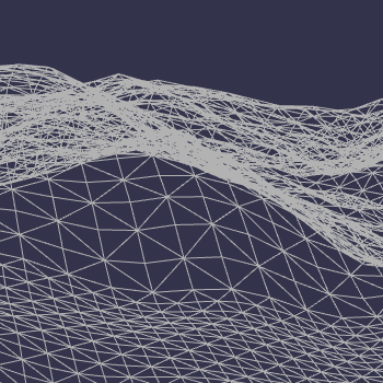
So Babylon JS currently does not have very robust terrain options especially with LOD considerations. After a little bit of side development I was able to have a decent algorithm be implemented. It was inspired by chunked quad-tree LOD system, but is slightly modified. I also used my Das_Noise library for the noise generation and will eventually make this system more robust and faster. I have not calculated to normals yet in a fashion that prevents lines between zones/leafs, but that should not be too hard to fix with a little time and focus. You can see the development thread here:
http://www.html5gamedevs.com/topic/31776-infinite-terrain-idea-bounce/

I also was working on a planetary version, but that I will post on later as its a little different then this algorithm.

http://www.babylonjs-playground.com/#f00M0U#39 for a good example of the LOD.

I will be finishing this up at some point optimizing the script and making fixes to get rid of the seam popping and the normal lines.

Universal IO – Development Experiment

Universal IO
Experimentation in a Timing Object

Here is a development log of trying to make a universal intensive operation timer. This is all pretty much off the top of my head. I’ll be making notes on here as localhost development proceeds throughout the day.

Step 1
Setting up our prototype object

**pseudo code

uIO = function(args){
	args = args || {};
	args.rate = args.rate || 1000/60;
	args.callback = args.callback || function(tick){ console.log('tick:'+tick); };
	this._init();
	return this;
};


uIO.prototype._init = function(){
	this._startedOn = (new Date()).getTime();
	this._lastTick = this._startedOn;
	this._io = null;	
};

var timer = new uIO();
console.log(timer);


Right away I start by defining a global scoped function that will be the instance of our timer when ever we need it. It is done this way so that we can have multiple instances of the same timer running on other objects on our page. Elements like canvas/dom animations, continuous polling events to the server, and other functions can be controlled from this object.

If we were to run this script on a page our console would just output the uIO object that was just created which is nothing fancy right now, but at least some sort of framework we can start building up is there!  What we need to do now is start the timeout loop and start having this “intensive operation” timer start doing something.

uIO = function(args){
	args = args || {};
	args.rate = args.rate || 1000/60;
	var self = this;
	args.callback = args.callback;
	args.holdStart = args.holdStart || false;
	this._init(args);
	return this;
};


uIO.prototype._init = function(args){
	this._startedOn = null;
	this._lastTick = null;
	
	this._loop = null;
	this._lastTick = null;
	this._lastFrame = null;
	this._delta = 0;
	this._tick = 0;
	this._fps = 0;
	
	this.active = false;
	this._rate = args.rate;
	
	if(!args.holdStart){
		this._start();
	}
};

uIO.prototype._start = function(){
	var now = (new Date()).getTime();
	this._startedOn = this._lastFrame = this._lastTick = now;
	var self = this;
	this.active = true;
	this._loop = setInterval(function(){
			self._run();
		}, 0);
};

uIO.prototype._run = function(){
	var now = (new Date()).getTime();
	if( now - this._lastFrame >= this._rate){
		this._RUN(now);		
	}
	this._tick++;
	this._lastTick = now;
};

uIO.prototype._RUN = function(now){		
		this._fps = (1000 / (now - this._lastFrame)).toFixed(0);
		this._delta = (now - this._startedOn) * 0.001;
		this._lastFrame = now;
};

var timer = new uIO();
console.log(timer);

Now we have something, with the additions just made the timer should now be able to run at a close to set amount and have a delta variable available to us.
This will be the core of the system for timing. The ext steps will be to include a callback that is interchangeable for the object to run when ever the _RUN function has fired.

Step 2
Debug and WP Set-up

What can we do with this new Object now? The first thing that comes to my mind is animations on a canvas element, or physic calculations that require a time step. In order to see if things are running according to principle I will take the new object and firstly have it output to a canvas element, and then refine the output to several different timing functions that can change the motion of an object or shape on the canvas. I am thinking the smartest way to do this for right now, will be include a new Object type under the scope of the uIO Object that will function as a debug output.

When starting these changes the first thing I want to do is go back to the uIO objects _init function and add “this._debugOn = false;”, so that there is a flag in the parent object for later use. Next I set up a new Object type:

/*-----DEBUG LAYER STUFF------*/
uIO.prototype.showDebug = function(target){
	if(!this._debugOn){
		this._debugOn = true;
		this._debugLayer = new uIO.DEBUG(target || null, this);
		
	};
};

uIO.DEBUG = function(target, parent){
	this._target = document.getElementById(target) || document.body;
	this._canvas = document.createElement('canvas');
	this._canvas.style.width = "100%";
	this._canvas.style.height = "100%";
	this._resize();		
};

uIO.DEBUG.prototype._resize = function(){
	this._canvas.width = this._canvas.offsetWidth, this._canvas.height = this._canvas.offsetHeight;
};
/*-----END DEBUG LAYER STUFF------*/

What was added was first a prototype of the uIO object which will control the parenting chain of the objects. In theory you could call the DEBUG object manually but this just keeps things tidy. Next the actual sub Object this is another function that now holds some information for our output canvas and a prototype method to make sure that the canvas has a resize function which I will later tie into a window resize event.

The thing that needs to happen now though, as the project is progressing because this is specifically for the purpose of documenting the development and demonstrating it on my website (which is powered by WordPress), I will need to start making changes to prepare my post to display these debug objects, and have access to the newly created uIO. In order to “hook” into the post with my own JavaScript Libraries fast and with the ability to update the script globally but choose which pages are even accessing the content I use the Scripts-n-Styles Plugin. This is a great plugin with “The Hoop’s” shortcodes it provides access to. After pasting the script into this section of the plugin it created me a shortcode [hoops name=”uIO-lib”], which I can now include in pages, or posts on my WP site. The technique I will use to access this can be directly on the post elements html or through another hooped shortcode that has a script that fires after the creation of the page, in order to ensure that all DOM content is accessible at the time of the creation of the uIO Object.

On my wordpress post, for example this one I need to create a target for the output canvas to go to otherwise it will default target the body of the document which is not the desired effect at this current moment for example:


<div id='output-target-example' style='display:block;width:600px;height:300px;border:1px solid lightgrey;'></div>

And if everything is going according to plan, you should see such container div above now, though nothing is outputting to it. Development at this point becomes a little bit different. What I am going to do is first modify my localhost page to kinda simulate the elements and situation that I am trying to accomplish on the publicly hosted version which makes it look like the following.

<body>
<div id='output-target-1' style='display:block;width:300px;height:300px;border:1px solid lightgrey;'></div>
<script>
/*---- MAIN LIB ----*/
uIO = function(args){
	args = args || {};
	args.rate = args.rate || 1000/60;
	var self = this;
	args.callback = args.callback;
	args.holdStart = args.holdStart || false;
	this._init(args);
	return this;
};


uIO.prototype._init = function(args){
	this._startedOn = null;
	this._lastTick = null;
	
	this._loop = null;
	this._lastTick = null;
	this._lastFrame = null;
	this._delta = 0;
	this._tick = 0;
	this._fps = 0;
	
	this.active = false;
	this._rate = args.rate;
	this._debugOn = false;
	
	if(!args.holdStart){
		this._start();
	}
};

uIO.prototype._start = function(){
	var now = (new Date()).getTime();
	this._startedOn = this._lastFrame = this._lastTick = now;
	var self = this;
	this.active = true;
	this._loop = setInterval(function(){
			self._run();
		}, 0);
};

uIO.prototype._run = function(){
	var now = (new Date()).getTime();
	if( now - this._lastFrame >= this._rate){
		this._RUN(now);		
	}
	this._tick++;
	this._lastTick = now;
};

uIO.prototype._RUN = function(now){		
		this._fps = (1000 / (now - this._lastFrame)).toFixed(0);
		this._delta = (now - this._startedOn) * 0.001;
		this._lastFrame = now;
		if(this._debugOn){this._debugLayer._DRAW()};
};


/*-----DEBUG LAYER STUFF------*/
uIO.prototype.showDebug = function(target){
	if(!this._debugOn){
		this._debugOn = true;
		this._debugLayer = new uIO.DEBUG(target || null, this);
		
	};
};

uIO.DEBUG = function(target, parent){
	this._parent = parent;
	this._target = document.getElementById(target) || document.body;
	this._canvas = document.createElement('canvas');
	this._canvas.style.width = "100%";
	this._canvas.style.height = "100%";
	this._target.appendChild(this._canvas);
	this._resize();	
};

uIO.DEBUG.prototype._resize = function(){
	this._canvas.width = this._canvas.offsetWidth, this._canvas.height = this._canvas.offsetHeight;
	this._ctx = this._canvas.getContext('2d');
};

uIO.DEBUG.prototype._DRAW = function(){
	var cvas = this._canvas;
	var cW = cvas.width, cH = cvas.height;
	var ctx = this._ctx;
	ctx.clearRect(0,0,cW,cH);
	ctx.font = "16px Arial";
	ctx.fillText("FPS:",0,18);
	ctx.fillText(this._parent._fps,60,18);	
};
/*-----END DEBUG LAYER STUFF------*/
/*---- END MAIN LIB ----*/


/*---- Page Script ----*/
document.addEventListener('DOMContentLoaded', function(){
	var test1 = new uIO();
	test1.showDebug('output-target-1');
	console.log(test1);
}, false);
/*---- END Page Script ----*/

</script>
</body>

By the way if anyone reading this is wondering how I am outputting the code without it running on the post simply wrap any section like that in <pre> for just JS code and then <pre><xmp> for anything that has HTML elements as well. Some styling will be needed to display that correctly but just a little tidbit if you were wondering. Now I need to update the script on the WP side so I go back to my Scripts and Style Admin section, and make the appropriate changes. I also have to create a new Hoop for the section that will interact with this specific page, like I said earlier this can be inline, but for ease of access I prefer to hook it in.

Time to give all this a shot, by now placing the Hoops on this post, and making sure that the element it is looking for in our Development page hook is available for it!

By the looks of it things are going well, I now have a small box that is displaying the fps, this can later be extended to do more but for now here we go. Now its time to create a new Object type that will be for drawing different variations of timing equations and different visualization based on what ever variables from the uIO objects timings. **The one thing I am noticing at this time is that on my system its saying 50fps and holding that pretty true, that is honestly wrong and I will have to go back to figure out if its the output or my actual frames/rate that is incorrect for now well just move on as this is a merely just a demonstration. If this we going to be a refined library this would need to be debugged at some point!

Step 3
Visualizing Output and Timings

Now that there is a Object that is generating both a tick time and a delta time, we can start doing some more advance testing. In addition after just implementing a basic canvas and drawing to it the dynamically changing fps variable I now have the option to create a new Object type for handling equations in the form of nested functions. This Object, will have a uIO object that is a child of itself and will be accessed by the uIO child in order to fire off its draw event or will create a uIO object with an assigned callback for accessing the parent Objects draw function… I know that might sound complicated but stick with me. For the time being, I am going back to localhost development in these next explanations.

<body>
<div id='output-target-1' style='display:block;width:200px;height:40px;border:1px solid lightgrey;'></div>
<div id='output-target-2' style='display:block;width:400px;height:100px;border:1px solid lightgrey;position:relative;'>
	<div id='debug-target-2' style='display:block;width:100px;height:32px;border:none;position:absolute;right:0;top:0;z-index:101;'></div>
</div>
<div id='output-target-3' style='display:block;width:400px;height:100px;border:1px solid lightgrey;position:relative;'>
	<div id='debug-target-3' style='display:block;width:100px;height:32px;border:none;position:absolute;right:0;top:0;z-index:101;'></div>
</div>
<div id='output-target-4' style='display:block;width:400px;height:100px;border:1px solid lightgrey;position:relative;'>
	<div id='debug-target-4' style='display:block;width:100px;height:32px;border:none;position:absolute;right:0;top:0;z-index:101;'></div>
</div>

<script>
/*---- MAIN LIB ----*/
uIO = function(args, parent){
	this._parent = parent || false;
	args = args || {};
	args.rate = args.rate || 1000/60;
	var self = this;
	args.callback = args.callback;
	args.holdStart = args.holdStart || false;
	this._init(args);
	return this;
};


uIO.prototype._init = function(args){
	this._startedOn = null;
	this._lastTick = null;
	
	this._loop = null;
	this._lastTick = null;
	this._lastFrame = null;
	this._delta = 0;
	this._tick = 0;
	this._fps = 0;
	
	this.active = false;
	this._rate = args.rate;
	this._debugOn = false;
	
	if(!args.holdStart){
		this._start();
	}
};

uIO.prototype._start = function(){
	var now = (new Date()).getTime();
	this._startedOn = this._lastFrame = this._lastTick = now;
	var self = this;
	this.active = true;
	this._loop = setInterval(function(){
			self._run();
		}, 0);
};

uIO.prototype._run = function(){
	var now = (new Date()).getTime();
	if( now - this._lastFrame >= this._rate){
		this._RUN(now);		
	}
	this._tick++;
	this._lastTick = now;
};

uIO.prototype._RUN = function(now){		
		this._fps = (1000 / (now - this._lastFrame)).toFixed(0);
		this._delta = (now - this._startedOn) * 0.001;
		this._lastFrame = now;
		if(typeof this._parent == 'object'){
			this._parent._DRAW();		
		}
		if(this._debugOn){this._debugLayer._DRAW()};
};


/*-----DEBUG LAYER STUFF------*/
uIO.prototype.showDebug = function(target){
	if(!this._debugOn){
		this._debugOn = true;
		this._debugLayer = new uIO.DEBUG(target || null, this);	
	};
};

uIO.DEBUG = function(target, parent){
	this._parent = parent;
	this._target = document.getElementById(target) || document.body;
	this._canvas = document.createElement('canvas');
	this._canvas.style.width = "100%";
	this._canvas.style.height = "100%";
	this._target.appendChild(this._canvas);
	this._resize();	
};

uIO.DEBUG.prototype._resize = function(){
	this._canvas.width = this._canvas.offsetWidth, this._canvas.height = this._canvas.offsetHeight;
	this._ctx = this._canvas.getContext('2d');
};

uIO.DEBUG.prototype._DRAW = function(){
	var cvas = this._canvas;
	var cW = cvas.width, cH = cvas.height;
	var ctx = this._ctx;
	ctx.clearRect(0,0,cW,cH);
	ctx.font = "16px Arial";
	ctx.fillText("FPS:",0,18);
	ctx.fillText(this._parent._fps,40,18);	
};
/*-----END DEBUG LAYER STUFF------*/
/*-----VISUALIZER------*/
VIZ = function(name, target, shape){
	this._name = name || "New Visualizer"
	this._target = document.getElementById(target) || document.body; 
	this._shape = VIZ.SHAPES[shape] || VIZ.SHAPES.SIN;
	this._init();
	
	return this;
};

VIZ.prototype._init = function(){
	this._io = new uIO({}, this);
	this._canvas = document.createElement('canvas');
	this._canvas.style.width = "100%";
	this._canvas.style.height = "100%";
	this._target.appendChild(this._canvas);
	this._resize();
};

VIZ.prototype._resize = function(){
	this._canvas.width = this._canvas.offsetWidth, this._canvas.height = this._canvas.offsetHeight;
	this._ctx = this._canvas.getContext('2d');
};

VIZ.prototype._DRAW = function(){
	var cvas = this._canvas;
	var cW = cvas.width, cH = cvas.height;
	var hw = cW*0.5, hh = cH*0.5;
	var ctx = this._ctx;
	ctx.clearRect(0,0,cW,cH);
	var _d = this._io._delta;
	var v = this._shape(_d);
	var posX = hw*v, height = cH*0.96;
	ctx.fillRect(hw, 3, hw*v, cH-3);
	
};


VIZ.SHAPES = {};
VIZ.SHAPES.SIN = VIZ.SHAPES['SIN'] = function(v){
	return Math.sin(v);	
};
VIZ.SHAPES.COS = VIZ.SHAPES['COS'] = function(v){
	return Math.cos(v);	
};
VIZ.SHAPES.TAN = VIZ.SHAPES['TAN'] = function(v){
	return Math.tan(v);	
};


/*-----END VISUALIZER------*/
/*---- END MAIN LIB ----*/


/*---- Page Script ----*/
document.addEventListener('DOMContentLoaded', function(){
	var test1 = new uIO({}, false);
	test1.showDebug('output-target-1');
	console.log(test1);
	
	var test2 = new VIZ('First-Test', 'output-target-2');
	test2._io.showDebug('debug-target-2');
	console.log(test2);
	
	var test3 = new VIZ('Second-Test', 'output-target-3', 'COS');
	test3._io.showDebug('debug-target-3');
	console.log(test3);
	
	var test4 = new VIZ('Second-Test', 'output-target-4', 'TAN');
	test4._io.showDebug('debug-target-4');
	console.log(test4);
	
}, false);
/*---- END Page Script ----*/

</script>
</body>

With these changes now on the local client things are starting to take shape. I had to make quite a bit of modification to the sections of the code, lets review the updates.

Now tomorrow, I will clean up the display of the visualizer and make it more dynamic and also work out some more timing equations!
To be Continued…

Das_Noise

Das_Noise was a project I started for procedural generation of noise through a native JavaScript library. It includes most standard noises and there are version floating around that I did with some odd ones as well. This should be the stable version on my github, if not then I will be fixing that momentary because I want to do a few experiments with it coming up soon.

If you use it please put this in the script somewhere:

/************************************************************************
Andrew V Butt Sr. – Pryme8@gmail.com
Pryme8.github.io
//Compilation of Standard Noises for Javascript version 1.1.0;
Special Thanks to Stefan Gustavson (stegu@itn.liu.se),
and Peter Eastman (peastman@drizzle.stanford.edu)
Some of this code was placed in the public domain by its original author,
Stefan Gustavson. You may use it as you see fit, but
attribution is appreciated.
*************************************************************************/

Vector2.js – Vector Library

Just include this js file. Call an new vector with:


new vec2(x,y);

All Methods are chainable.

copy(vec) - Copy Values from one vec2 to other.
vec => vec2
return => vec

clone() - Make new vec2 from a vec2
return => new vec2

perp() - Get the Perpendicular angle;
return => vec2

rotate(angle) - Rotate a vec by an angle in radians.
angle => float
return => vec2

reverse() - Reverse the Vector
return => vec2

normalize() - Normalize the Vector
return => vec2

add(input) - Add a vec2
input => vec2
return => vec2

subtract(input) - Subtract other vec2 input => vec2 return => vec2

scale(x,y) - Scale vec2 by X or X and Y
x=> float
y=> float || null
return => vec2

dot(input) - Dot product between two vectors;
input => vec2
return (this.x * input.x + this.y * input.y)

len2() - Length of Vector^2
return this.dot(this);

len() - Length of Vector
return => return Math.sqrt(this.len2());

project(axis) - Project a vector onto anouther.
axis => vec2
return => vec2

projectN(axis) - Project onto a vector of unit length.
axis => vec2
return => vec2

reflect(axis) - Reflect vector to a vector.
axis => vec2
return => vec2

reflectN(axis) - Reflect on an Arbitrary Axis
axis => vec2
return => vec2

getValue(v) - Returns value of float or array,
v => ('x' || 0) || ('y' || 1) || null;
return => Float || Array(2);

——————————————————–
Any Question feel free to email me at Pryme8@gmail.com